How to Choose a Compact Transformer Substation?

Choosing a Compact Transformer Substation is not simply a matter of selecting the smallest available enclosure. Size matters, but reliability, safety, service access, and future demand matter more. A unit that fits today may become a costly limitation after one production line expands. That possibility deserves attention.

John D. McDonald, a recognized power-system protection specialist, offers a useful principle: “Reliability is the most important attribute of a protection system.” His statement applies directly here. A compact design must coordinate transformers, switchgear, relays, grounding, and protection settings as one system. A small footprint cannot justify weak fault protection.

Begin with the site conditions. Record the incoming voltage, expected load, short-circuit level, ambient temperature, humidity, and available clearance. Check whether the substation will serve a factory, commercial building, renewable installation, or temporary project. Each application creates different thermal and operational demands. A dry-type transformer may suit an indoor plant where fire risk and ventilation matter. An oil-immersed unit may offer better efficiency and capacity in a properly controlled outdoor location.

Examine the enclosure rating, corrosion protection, cable entry, noise level, and maintenance space. Look closely. Technicians need room to test connections without working against sharp panels or crowded compartments. Confirm compliance with applicable IEC or local standards, including transformer and medium-voltage switchgear requirements.

There is no perfect configuration. A cheaper design may reduce initial cost but increase downtime later. The better choice balances present performance with uncertain growth, maintenance skill, climate, and replacement access. Careful comparison turns a Compact Transformer Substation from a space-saving product into dependable electrical infrastructure.
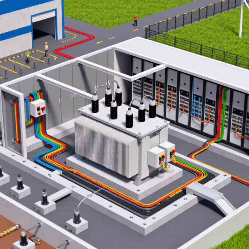
How to Choose a Compact Transformer Substation?

Define the Electrical Load and Voltage Requirements

Choosing a compact transformer substation starts with an accurate electrical load assessment. Walk through the site and list every major load, including pumps, motors, lighting, HVAC units, and future equipment. Record each rating in kilowatts, operating hours, starting current, and duty cycle. A neat spreadsheet can still be wrong.

Separate continuous loads from intermittent loads, then apply realistic demand and diversity factors. Large motors may draw several times their running current during startup. That brief surge can cause voltage dips, nuisance trips, or transformer overheating. Calculate apparent power in kVA, not only connected kW. For three-phase systems, use the measured line voltage, current, and power factor. Field measurements are valuable because drawings often show planned equipment, not actual operation.

Confirm the incoming utility voltage, frequency, grounding arrangement, and available fault level with qualified electrical personnel. Then define the required secondary voltage and phase configuration for the site. A 400-volt three-phase system suits some facilities, while sensitive equipment may require separate circuits or tighter voltage control. Select a transformer rating that covers verified demand, starting conditions, and reasonable expansion. Avoid excessive oversizing; it increases cost and may reduce efficiency at light loads. A practical margin is useful, but I would review it rather than accept a fixed percentage blindly. Recheck cable capacity, protection settings, enclosure rating, and local code requirements before ordering.

Compare Compact Transformer Substation Configurations

How to Choose a Compact Transformer Substation?

Compare Compact Transformer Substation Configurations

A single-transformer configuration suits small commercial buildings and light industrial loads. It usually needs less space and simplifies protection coordination. A 630 kVA unit may fit beside a service road, but access for lifting still matters. Check future load growth before selecting it. A small footprint can become a serious limitation later.

A dual-transformer configuration provides better capacity and operational flexibility. One transformer can continue supplying essential circuits during maintenance. However, it increases cost, heat release, cable complexity, and protection requirements. Ring-main configurations improve supply continuity when the network has two available feeders. They also require careful switching procedures and trained operators. More equipment does not always mean better reliability.

Air-insulated layouts are easier to inspect and repair. They generally require more clearance and a larger enclosure. Gas-insulated layouts save space and resist dust, moisture, and salt exposure. Their maintenance can be more specialized. A compact substation should also be compared by transformer type, cooling method, fault level, noise, and fire separation. Engineers should verify soil conditions, cable bending space, ventilation, earthing, and local electrical rules. Field inspections often find blocked doors or undersized cable trenches. These details are easy to miss. The best configuration balances present demand, expansion plans, site conditions, and the skills of the maintenance team.

Evaluate Site Conditions, Capacity, and Safety Standards

Choosing a compact transformer substation starts with the site, not the equipment catalogue. Measure available space, access routes, soil strength, drainage, and flood exposure. A unit may fit on paper yet fail during delivery or maintenance. Leave working clearances around doors, cable trenches, ventilation openings, and lifting points. Noise matters near homes, offices, and hospitals. Check ambient temperature, altitude, humidity, dust, and salt exposure before selecting the enclosure rating.

Capacity must reflect both present demand and realistic growth. Review load profiles, motor starting currents, harmonics, and the required voltage ratio. Oversizing wastes money and can reduce operating efficiency. Undersizing creates overheating and nuisance trips. I have seen projects rely on average demand alone. That was a mistake. Peak loads revealed the problem later. Allow practical spare capacity, but do not guess. Confirm transformer impedance, short-circuit levels, protection coordination, and standby requirements with a qualified engineer.

Safety should follow applicable local electrical codes and recognized standards, such as IEC 62271-202 and IEC 60076 where relevant. Specify earthing, touch-voltage control, internal arc protection, fire separation, secure access, and clear warning labels. Check emergency isolation and safe maintenance procedures. Keep combustible materials away. Test protection settings before energization. Documentation is part of safety. Include drawings, test records, inspection schedules, and training instructions. A compact design is not automatically a safe design. Recheck assumptions with the utility and an independent electrical professional.

How to Choose a Compact Transformer Substation? - Evaluate Site Conditions, Capacity, and Safety Standards

Evaluation Dimension Recommended Requirement Typical Compact Substation Data Why It Matters Selection Check
Rated Capacity Select a transformer that covers the calculated maximum demand plus future growth. 100–2,500 kVA for common compact distribution applications. Prevents overheating, nuisance tripping, and premature insulation aging. Target operating load at approximately 70–85% of nameplate capacity under normal peak conditions.
Load Growth Allowance Include expected expansion, additional equipment, and changes in operating schedules. Common planning margin: 15–25% above present calculated demand. Reduces the likelihood of an early transformer replacement or costly site modification. Document present load, forecast load, motor starting demand, and non-linear loads.
Primary Voltage Match the utility or incoming medium-voltage system. Typical distribution levels include 6.6 kV, 10 kV, 11 kV, 13.8 kV, and 20 kV. Incorrect voltage selection can make the equipment unsafe or incompatible with the network. Confirm nominal voltage, highest system voltage, frequency, and utility fault level.
Secondary Voltage Match the voltage required by the site's distribution boards and end-use equipment. Common low-voltage outputs include 400/230 V or 415/240 V, three-phase, four-wire. Ensures correct equipment operation and limits voltage conversion losses. Verify phase arrangement, neutral requirements, grounding method, and permissible voltage tolerance.
Installation Location Choose indoor, outdoor, or semi-outdoor construction according to exposure and access conditions. Outdoor enclosures commonly use an ingress protection rating of IP54 or higher, subject to the site environment. Protects energized parts from water, dust, accidental contact, and environmental damage. Assess rain, dust, salt spray, corrosive gases, solar radiation, and flooding risk.
Available Footprint Allow room for ventilation, cable bending, inspection, maintenance, and safe working clearances. A compact package may occupy roughly 3–12 m², depending on rating and switchgear arrangement. A small footprint is useful only if operators can safely access and service the equipment. Confirm layout drawings, door swing, emergency access, cable routes, and local clearance rules.
Ambient Temperature Use the manufacturer's rated ambient range and apply derating where necessary. Many standard designs are based on a maximum ambient temperature near 40°C, subject to the applicable standard. High temperature reduces permissible loading and accelerates thermal aging. Check maximum, minimum, daily average, altitude, ventilation, and solar heat gain.
Cooling Method Select natural air cooling or liquid cooling based on capacity, noise, fire risk, and maintenance needs. Dry-type transformers are often used indoors; liquid-immersed units are common where higher capacity or outdoor installation is required. Cooling affects efficiency, enclosure design, fire protection, and service intervals. Evaluate heat dissipation, ventilation openings, liquid containment, and local fire regulations.
Short-Circuit Withstand The assembly must withstand the prospective fault current at the installation point. Low-voltage switchboards may be specified with short-circuit ratings such as 25 kA or 50 kA for a defined duration, subject to system calculations. Adequate withstand capability limits equipment damage and arc-fault consequences. Obtain the utility fault-current figure and coordinate protective-device ratings.
Protection Functions Provide protection against overload, short circuit, earth fault, overtemperature, and abnormal voltage where applicable. Typical equipment includes medium-voltage fuses or circuit breakers, low-voltage main breakers, and temperature monitoring. Coordinated protection isolates faults while maintaining service to unaffected circuits. Review selectivity, relay settings, backup protection, and emergency shutdown arrangements.
Grounding and Bonding Bond all exposed conductive parts and design the earth system according to fault-current and touch-voltage calculations. The installation normally includes an earth grid or electrode system, protective bonding conductor, and neutral grounding arrangement. Reduces electric-shock risk and provides a controlled path for fault current. Verify soil resistivity, earth resistance targets, step and touch voltage, and testing access.
Safety Interlocking Prevent unsafe switching, access to live compartments, and opening of doors under hazardous conditions. Common features include key or mechanical interlocks, door locks, shutters, earthing switches, and position indicators. Interlocks reduce the risk of incorrect operation and accidental contact with energized components. Confirm the switching sequence and test each interlock during commissioning.
Applicable Standards Use the standards required by the project jurisdiction, utility, and authority having jurisdiction. Common references include IEC 62271 for high-voltage switchgear, IEC 60076 for power transformers, IEC 61439 for low-voltage assemblies, and IEEE C57 series where applicable. Standards define design, testing, insulation, temperature-rise, fault withstand, and operational requirements. Request routine-test reports, type-test evidence where required, drawings, and conformity documentation.
Noise Level Meet building, occupational, and environmental noise limits at the site boundary or occupied areas. Transformer sound levels commonly fall near 50–70 dB(A), depending on rating, cooling, and measurement conditions. Noise can affect offices, residences, hospitals, and other sensitive locations. Obtain guaranteed sound data and evaluate barriers, vibration isolation, and operating load.
Maintenance Access Provide safe access for inspection, testing, cable termination, replacement, and cleaning. Front-access designs can reduce room depth; rear access may still be required for certain cable and transformer arrangements. Poor access increases outage duration and creates additional worker-safety hazards. Review maintenance intervals, lifting points, spare-part requirements, and safe isolation procedures.
Fire and Spill Protection Provide fire separation, detection, suppression, and liquid containment when required by the installation type. Liquid-filled units may require a bund or containment volume sized according to local code and environmental risk assessment. Limits fire spread and prevents insulating liquid from entering soil or drainage systems. Check liquid type, fire point, spill pathway, drainage, separation distance, and emergency response plan.
Design Note: Final selection should be verified by a qualified electrical engineer using the site's load study, fault-current calculation, grounding study, environmental assessment, and applicable local electrical and fire-safety requirements.

Select Key Equipment, Protection, and Monitoring Features

How to Choose a Compact Transformer Substation?

Select Key Equipment, Protection, and Monitoring Features

A compact transformer substation should fit the site without sacrificing maintainability. Measure the available footprint, cable routes, ventilation paths, and working clearances before selecting equipment. A correctly rated transformer is essential, but it is not the only decision. Check load profiles, starting currents, ambient temperature, altitude, and future expansion. Medium-voltage switchgear should match the system voltage, fault level, and switching duty. Include surge arresters and a dependable earthing system. Small spaces leave little room for installation errors.

Protection deserves practical attention. Use correctly coordinated fuses or circuit breakers, overcurrent relays, earth-fault protection, and transformer temperature protection. Current and voltage transformers must provide suitable accuracy for both protection and metering. Arc-resistant construction may improve operator safety where the risk assessment requires it. Interlocking should prevent unsafe switching sequences. A tidy panel is not automatically a safe panel.

Monitoring features can reveal problems before an outage occurs. Consider winding temperature, oil temperature, oil level, humidity, breaker position, and load current sensors. For critical sites, partial-discharge monitoring and remote alarms can add valuable warning time. Communication should use secure, documented protocols with clear alarm priorities. During commissioning, test every trip circuit and simulate sensor failures. Field inspections often show that installation details matter more than a polished specification. I have seen cable bending limits overlooked. That small mistake can create long-term stress, heat, and maintenance trouble. Regular thermal inspections and protection testing keep the substation dependable.

Review Installation, Maintenance, and Future Expansion Needs

Choosing a compact transformer substation should begin with the site, not the catalog. Check access for delivery vehicles, lifting equipment, drainage, ventilation, and required working clearances. A narrow enclosure may fit the drawing but fail during cable termination or emergency repair. Leave room for safe movement. That detail matters.

The U.S. Department of Energy’s 2022 Electric Grid Supply Chain Review reported distribution-transformer lead times extending from several months to one or two years. Confirm equipment availability before finalizing the construction schedule. During installation, inspect foundation levels, cable bending space, earthing continuity, and protection settings. Record torque values and test results. Small omissions become expensive later.

Maintenance planning should include infrared inspections, enclosure checks, corrosion monitoring, relay testing, and periodic cleaning. For oil-filled equipment, schedule leak checks and insulation-fluid testing. For dry-type units, keep ventilation paths clear and monitor dust accumulation. The International Energy Agency’s Electricity 2024 report expects global electricity demand to grow by about 4% annually through 2026. Future loading may arrive sooner than expected. Reserve switchgear space, spare cable routes, and foundation capacity for an additional transformer or feeder. This is often overlooked. My own preference is to design for measured expansion, not unlimited capacity; oversizing wastes space and capital, while underestimating growth can force disruptive replacement. Recheck the load forecast every few years.